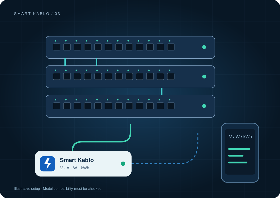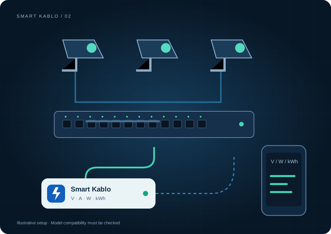
Smart Kablo can measure and control a compatible recorder or PoE switch supply. It does not replace camera, recording-application or disk monitoring. A restart creates a recording interruption and needs a controlled procedure.
How much electricity does a CCTV system use?
The complete load includes the recorder, disks, PoE cameras and separate adapters. A measurement on the NVR cable excludes cameras powered by another switch. Night-time infrared illumination and disk activity can also change demand.
Capture kWh across at least one full day and night. Record the camera count, disk count and the source of PoE power. Use daily totals to assess the month instead of extrapolating a single instant watt reading.
Which equipment can be considered?
| Equipment / measurement point | Measurement boundary | Commissioning check |
|---|---|---|
| NVR / DVR | Recorder and loads on the same inlet | C14 inlet and rated input including disks and PoE |
| PoE switch | Switch and cameras powered by it | Total PoE demand and startup current |
| Adapter-powered camera | Compatible adapter AC side only | A C13 connector does not fit a 12 V DC socket |
Some recorders use an external DC adapter. The C13 output cannot connect to a DC input; the adapter’s AC inlet must also fit. Plan UPS coverage and recording redundancy separately when continuity is required.
Connector and load checks
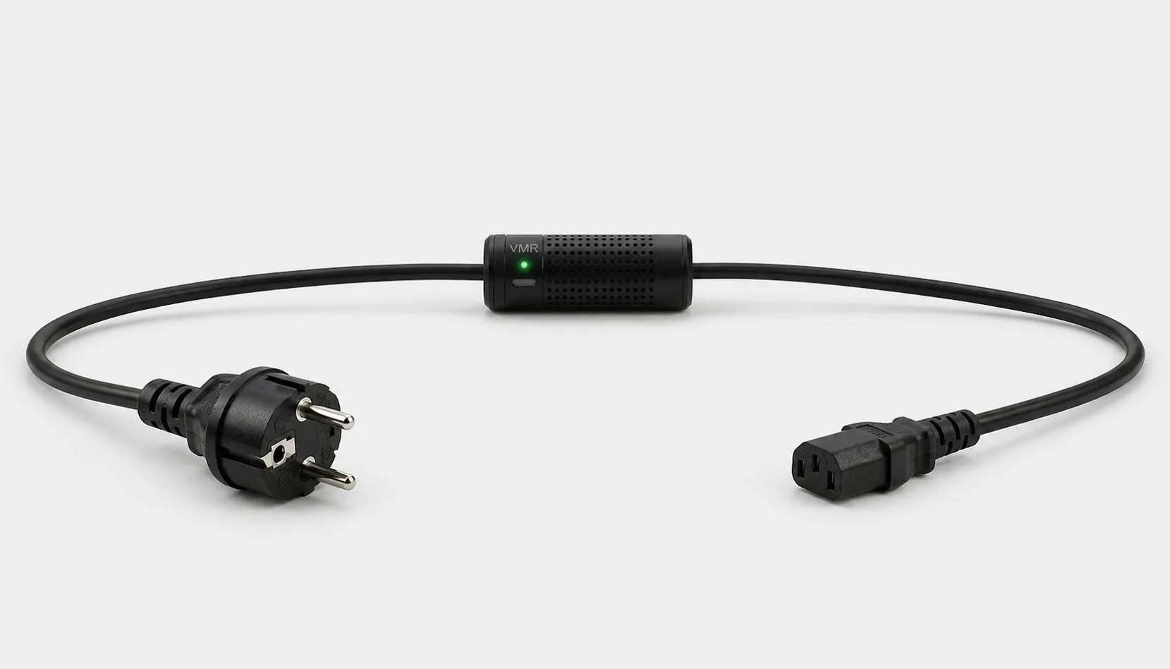
The current C13-output Smart Kablo requires a C14 equipment inlet. Assess rated input, startup demand and continuous load against the 5 A limit. At 230 V, 5 A corresponds to 1,150 VA of apparent power; this is not a blanket 1,150 W load approval. Do not assume a direct fit with C5, C7, DC or other locking connectors.
Read the IEC connector guide →How should a recorder be restarted remotely?
- Check the viewing client and the recorder’s own management interface first.
- Agree an authorised maintenance window if recording is active.
- Use the software reboot or graceful shutdown command and wait for the manufacturer’s completion indication.
- If supply intervention is necessary, record the outage. Then verify live video, recording schedules and disk health.
Removing power with a relay is not a graceful recorder shutdown. It can interrupt disk writes and recordings. A nightly power-off schedule is unsuitable for a system that must record continuously.
Remote Smart Cloud / Android control needs working Wi-Fi, internet access and authorised account access. Local interfaces and integrations depend on the installed version and network design.
Electricity use and cost calculator
The example assumes an average of 60 W for the whole measured supply. Running for 24 hours over 30 days gives 43.2 kWh. This is not a test result derived from a camera count. Replace it with the actual recorder and PoE measurement boundary.
Cost = measured kWh × your electricity rate
A protection layer at the supply
Automatic relay cutoff on overvoltage
When overvoltage is detected, Smart Kablo automatically switches the relay off and disconnects the connected equipment supply. This adds a protection layer that helps limit exposure to excessive voltage.
- 01Overvoltage detected
- 02Relay switches OFF
- 03Equipment supply disconnected
Automatic cutoff helps limit overvoltage exposure for the recorder and loads fed from that output. Recording may stop while the supply is disconnected, so electrical protection and recording continuity must be planned together.
Verify the protection threshold and restoration behaviour in the installed device settings. This function does not supply backup power or guarantee protection against lightning or every transient surge. Assess required UPS and suitable surge-protection hardware separately.
Start with a small pilot
Start with one recorder. Document day and night demand, camera feeds and UPS coverage. Test intervention in a maintenance window. After power returns, confirm that new recordings are being written, not merely that live video appears.
Document the actual model, inlet, nameplate current and startup behaviour before extending the rollout. Product documents · Controlled power intervention guide
Frequently asked questions
Should CCTV be powered off every night to save energy?
The recording requirement comes first. Do not schedule supply interruptions when 24/7 recording is required. Measure first and assess unnecessary loads separately from the recording function.
Does an NVR reading include all cameras?
It includes cameras supplied by that NVR’s PoE outputs. Cameras using a separate switch or adapter require a separate measurement.
Can Smart Kablo identify a failed disk or missing video?
Power measurements cannot establish those faults by themselves. Check disk health, recording schedules and camera connectivity through recorder software or a separate monitoring system.
What does Smart Kablo do when overvoltage is detected?
When overvoltage is detected, Smart Kablo automatically switches the relay off and disconnects the connected equipment supply. This adds a protection layer that helps limit exposure to excessive voltage. Verify the protection threshold and restoration behaviour in the installed device settings. This function does not supply backup power or guarantee protection against lightning or every transient surge. Assess required UPS and suitable surge-protection hardware separately.