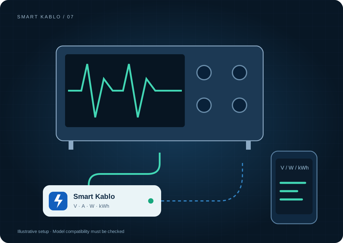
Smart Kablo measures the AC energy used by compatible test equipment and controls its supply. It does not measure probe signals, output energy or calibration performance. End an active experiment before planned supply intervention.
Input energy is different from the experiment’s measurement.
The kWh measured at a bench power supply’s AC input is not the energy delivered to the circuit under test. It also includes the instrument’s losses and idle demand. For an oscilloscope, Smart Kablo observes the instrument supply rather than the signal on its probes.
Keep start and finish conditions consistent between experiments. State whether warm-up, preparation and data saving are included. Results from different measurement boundaries should not be compared as if they describe the same test.
Which equipment can be considered?
| Equipment / measurement point | Measurement boundary | Commissioning check |
|---|---|---|
| Oscilloscope / analyser | Instrument AC input energy | C14 inlet, front-panel startup and warm-up |
| Bench power supply | Total energy drawn from the mains | Safe output shutdown and electrical load |
| Test computer | Separate computer consumption | Measurement files, logging and OS shutdown |
This scenario concerns electronic test equipment. Motor-driven, heated or differently classified laboratory equipment is not automatically included. Assess the manufacturer’s procedure and electrical limits for the actual device.
Connector and load checks
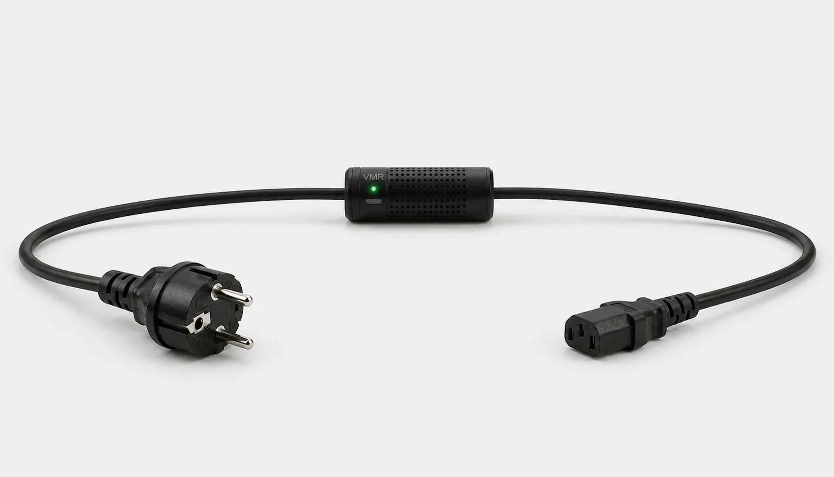
The current C13-output Smart Kablo requires a C14 equipment inlet. Assess rated input, startup demand and continuous load against the 5 A limit. At 230 V, 5 A corresponds to 1,150 VA of apparent power; this is not a blanket 1,150 W load approval. Do not assume a direct fit with C5, C7, DC or other locking connectors.
Read the IEC connector guide →How do you make the energy measurement repeatable?
- Write down the boundary: one instrument, computer included, warm-up included?
- Prepare the instrument as specified and record the initial kWh reading.
- Run the same test conditions and log active and idle periods.
- Make outputs safe, save results and calculate the difference from the final meter reading.
Restoring AC does not guarantee the instrument leaves front-panel standby. Remote control must not bypass calibration or safety interlocks. Evaluate the consequences of interruption before designing automated cutoff during a test.
Remote Smart Cloud / Android control needs working Wi-Fi, internet access and authorised account access. Local interfaces and integrations depend on the installed version and network design.
Electricity use and cost calculator
The example assumes one instrument averaging 80 W for 6 hours and 3 W at other times. Over 30 days this gives 16.02 kWh. It is not a RIGOL test result. Use actual experiment durations and input measurements.
Cost = measured kWh × your electricity rate
A protection layer at the supply
Automatic relay cutoff on overvoltage
When overvoltage is detected, Smart Kablo automatically switches the relay off and disconnects the connected equipment supply. This adds a protection layer that helps limit exposure to excessive voltage.
- 01Overvoltage detected
- 02Relay switches OFF
- 03Equipment supply disconnected
Automatic supply disconnection on detected overvoltage helps limit exposure of the instrument. Because interruption can end a test, prepare data-saving and recovery procedures separately for critical measurements.
Verify the protection threshold and restoration behaviour in the installed device settings. This function does not supply backup power or guarantee protection against lightning or every transient surge. Assess required UPS and suitable surge-protection hardware separately.
Start with a small pilot
Repeat one experiment three times on a selected instrument. Record duration, environment, warm-up and the kWh difference. Measure idle-on use separately between experiments. Report this as supply-energy data rather than instrument calibration evidence.
Document the actual model, inlet, nameplate current and startup behaviour before extending the rollout. Product documents · Controlled power intervention guide
Frequently asked questions
Does Smart Kablo measure like an oscilloscope?
No. It monitors supply voltage, current, power and energy for the connected equipment. It does not capture probe signals or high-frequency waveforms.
Is a power supply’s input kWh the output energy?
No. AC input includes the instrument’s own demand and losses. Energy delivered to the circuit under test requires a suitable separate output measurement.
What should stay constant between energy comparisons?
Keep the measurement boundary, warm-up time, load profile and recording start and finish conditions consistent. Do not directly compare results with different boundaries.
What does Smart Kablo do when overvoltage is detected?
When overvoltage is detected, Smart Kablo automatically switches the relay off and disconnects the connected equipment supply. This adds a protection layer that helps limit exposure to excessive voltage. Verify the protection threshold and restoration behaviour in the installed device settings. This function does not supply backup power or guarantee protection against lightning or every transient surge. Assess required UPS and suitable surge-protection hardware separately.